STO (Safe Torque Off)
STO Safety instructions


|
|
If the safety function STO is automatically activated by a control system, then make sure that the output of the control is monitored for possible malfunction. The monitoring can be used to prevent a faulty output from unintentionally activating the STO function. |
|
|
It is not possible to perform a controlled brake if the drive controlled STO is off. If controlled braking before the use of the STO function is necessary, the drive must be braked and the STO input must be disconnected from +24 V time-delayed. |
|
|
In case of a specific double fault within a very short time a single movement of a maximum angle of 120° (electrical) can happen. This effect can only happen if the drive is in the function STO. Even if the STO function will be issued for a whole year, this event will only happen every 100 Billion years. |
|
|
The STO Status signals are informal and not relevant for functional safety. |


Use as directed
The STO function is exclusively intended to provide a functional safe torque off of the motion system. To achieve this functional safety, the wiring of the safety circuits must meet the safety requirements of IEC 60204, ISO 12100 and ISO 13849.
STO inputs must be connected to the exit of a safety control or a safety relay, which at least meets the requirements of PLd, CAT 3 according to ISO 13849.
The 24 VDC supply unit for global and local STO supply must accord to PELV (EN 60204-1) requirements and must not be used for drive power supply.
Prohibited use
The STO function must not be used if the drive is to be made inactive for these reasons:
- Cleaning, maintenance and repair operations, long inoperative periods. In such cases, the entire system should be disconnected from the supply and secured (main switch).
- Emergency-Off situations. In an Emergency-Off situation, the main contactor is switched off (by the Emergency-Off button).
Wiring the system with hybrid cables from other manufacturers than Kollmorgen is not allowed. Changing cables or connectors is not allowed.
MKD-N have not to be used for driving elevators.
Do not use STO Status signals for functional safety.
Enclosure, wiring
For MKD-C/N observe the required ambient conditions.
The MKD-C/N (IP 20) must be mounted in an IP54 cabinet to ensure pollution level 2 according to IEC 60664-1. Connector X16/X26 (STO signals) ensures requirements of pollution level 3 according to IEC 60664-1.
For AKD-N refer to the ambient conditions described in the AKD-N Installation Manual. The AKD-N can be used in an environment that requires IP67 devices.
Wiring inside the cabinet
Wiring remaining must meet the requirements of the standard IEC 60204-1. In compliance with the safety standard ISO 13849-2 Table D.4; short-circuits between conductors or of any conductor to an exposed conductive part can be excluded when:
- permanently connected (fixed) and protected against external damage, e. g. by cable ducting, armouring, or
- within separate multicore cables, or
- within the IP54 electrical enclosure, or
- individually shielded with earth connection.
This is valid for the STO wiring of MKD-C and MKD-N.
Wiring outside the cabinet
If you are wiring leads that are outside the specified enclosure (IP54), the cables must be laid durably (firmly), protected from outside damage (for example, by laying the cable in a duct), placed in different sheathed cables, or protected individually by grounding connection.
Maximum cable length
Maximum cable length for safety relevant I/Os and for the 24 V supply (PELV) is 30 m.
Topology overview
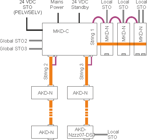
- MKD-C connector X16:
- global STO (String 2/3) inputs of the system powered by this MKD-C.
- MKD-C connector X15A:
- global STO (String 2/3) status output of the system powered by this MKD-C.
- MKD-N connector X26:
- local STO (axis 1 and axis 2 if built-in) input of the drive module.
- AKD-N connectors X3/X6:
- local STO input (X6) and status output (X3) of the AKD-N-DS/DT drive modules.
OSSD test pulses
Safety controllers usually check their outputs periodically during the normal operation. These test procedures create pulses to the STO-Enable inputs.
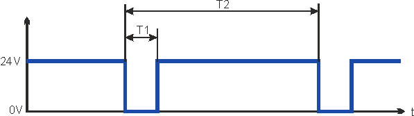
Test pulses with T1 ≤ 300 µs and T2 ≥ 200 ms will not have any influence to the safety relevant STO function. Test pulses, which are outside of this specification, will switch the STO function, but will not create a dangerous situation.
STO 24 VDC voltage supply
Use a PELV power supply for both global and local STO 24V DC supply.
|
STO 24 VDC supply |
|
Safety characteristic data
The STO safety implementation on the MKD-C, MKD-N and AKD-N is certified. The safety circuit implementation used for the safety function "Safe Torque Off" in the drive is suited for SIL 2 according to IEC 62061 and PLd / CAT3 according to ISO 13849-1.
Resulting Functional Safety classification (SIL and/or PL level) must be calculated across the drive system.
Safe Torque Off (STO) string type (global)
|
Structure |
STO |
ISO |
MTTFd |
IEC |
PFH |
SFF |
TM |
|---|---|---|---|---|---|---|---|
|
MKD-C + 1 x AKD-N |
global |
PL d, CAT 3 |
≥ 100 |
SIL 2 |
1.86E-08 |
94.2 |
20 |
|
MKD-C+ 14 x AKD-N |
global |
PL d, CAT 3 |
≥ 100 |
SIL 2 |
1.86E-08 |
94.2 |
20 |
|
MKD-C + |
global |
PL d, CAT 3 |
≥ 100 |
SIL 2 |
3.72E-08 |
94.2 |
20 |
Safe Torque Off (STO) local drive type (local)
|
Structure |
STO |
ISO |
MTTFd |
IEC |
PFH |
SFF |
TM |
|---|---|---|---|---|---|---|---|
|
14 x MKD-N (single axis) |
local |
PL d, CAT 3 |
≥ 100 |
SIL 2 |
3.97E-07 |
98.3 |
20 |
|
14 x MKD-N (dual-axis) |
local |
PL d, CAT 3 |
≥ 100 |
SIL 2 |
5.88E-07 |
98,.3 |
20 |
|
28 x MKD-N (single axis) |
local |
PL d, CAT 3 |
≥ 100 |
SIL 2 |
7.94E-07 |
98.3 |
20 |
|
MKD-C + |
local |
PL d, CAT 3 |
≥ 100 |
SIL 2 |
2.9E-08 |
95.9 |
20 |
|
MKD-C + |
local |
PL d, CAT 3 |
≥ 100 |
SIL 2 |
4.12E-07 |
95.9 |
20 |
Response Time
Local STO (MKD-N)
The delay from falling edge at local STO Enable input until energy supply to the motor is interrupted is maximum 10 ms.
Global STO (Strings 2/3, AKD-N)
The delay from falling edge at global STO Enable input until energy supply to the motors is interrupted, depends on the number of connected MKD-N to the string. Maximum reaction time is 10 ms. The more MKD-N are connected to the string, the shorter is the reaction time.
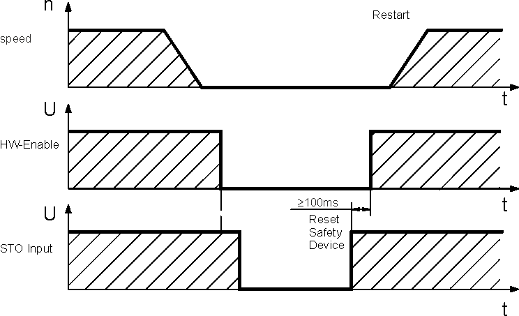
Signal diagram (sequence)
The diagram below shows how to use global STO function for a safe drive stop and fault free operation of the drives connected to one of the strings.
- Brake the drives in a controlled manner (speed setpoint = 0 V).
- When speed = 0 rpm, disable the drives (Enable = 0 V).
- Activate the STO function (STO input = 0 V)
- For restart you must reset the safety device.
Based on the standards according to EN60204-1 or EN 13849-1, you must implement a restart interlock. The design and execution depends on the respective risk assessment of the application and its safety level as well as safety rating.